
01
Exhaust pipes
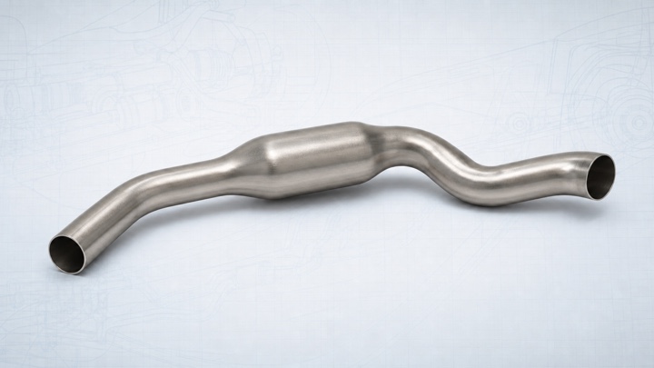
The image shows a formed core tube with trimmed ends and a continuous hollow flow path; the bend route, end interfaces, and later cutting remain project-specific.
Automotive Tube Hydroforming
ShuiYiYuan supports automotive components from drawing and forming-route review through hydroforming die development, tryout parts, sample confirmation, contract processing, and repeat production.
Project experience covers exhaust pipes, chassis and body structures, seat frames, and instrument-panel crossmembers.
Confirmed automotive experience
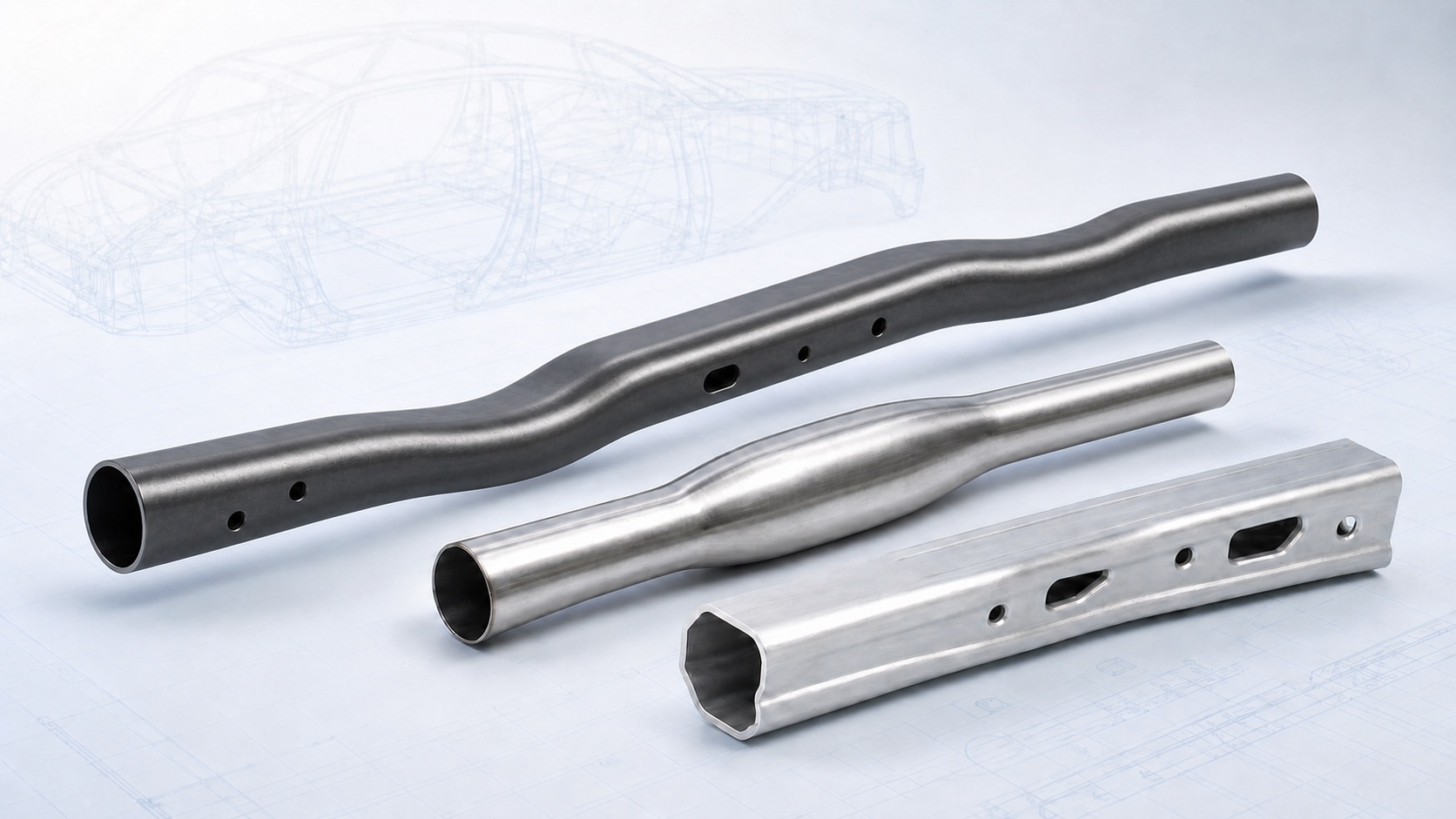
Confirmed work covers four groups: exhaust pipes, chassis and body structures, seat frames, and instrument-panel crossmembers. The cards below separate chassis and body examples so their geometry is easier to review.
The image shows a formed core tube with trimmed ends and a continuous hollow flow path; the bend route, end interfaces, and later cutting remain project-specific.
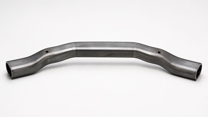
This is the formed core of a front-subframe reinforcement crossmember. The two small holes represent later cutting; it is not a complete subframe assembly.
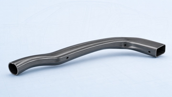
This representative hollow body member shows a continuous transition from round tube to a closed non-round section. The holes are secondary features.
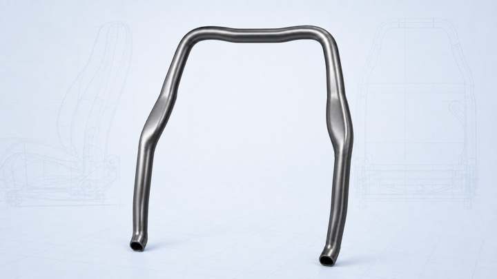
The illustration covers one variable-section inverted-U backrest frame. A complete seat frame normally adds separately made crossmembers, brackets, and welded assemblies.
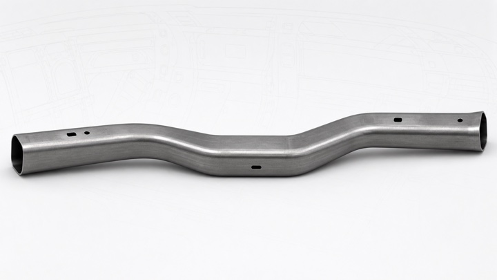
This is a formed hollow cross-car beam with restrained later-cut holes. Steering, HVAC, electronics, brackets, and body attachments are not shown.
Project handoff
The quotation states what enters the project, what ShuiYiYuan completes, and the condition of the samples or production parts delivered to the next operation.
Confirm the drawing revision, material grade, starting tube or preform, quantity, and critical interfaces.
Complete die development, tryout, sample parts, contract processing, repeat production, or tooling customization as required.
Deliver hydroformed blanks, parts with agreed trim or features, confirmed sample sets, or released production parts.
Engineering review
Hydroforming suitability depends on the target geometry, material and tube, interfaces, sample requirements, and production quantity.
Section transitions, local features, end conditions, radii, and removal from the die affect the tooling concept.
Grade, condition, wall thickness, seam state, and completed bending or preforming affect the available forming path.
Holes, trim lines, brackets, assembly zones, and validation requirements should be identified before die development.
Sample checks, expected volume, and delivered condition shape the tryout scope and repeat-production plan.
If a part only needs conventional tube bending, or the target geometry cannot be formed within the material’s workable range, we will identify the issue and discuss route changes.
From tool to released part
Die development turns the drawing and incoming tube into a forming route. Tryout establishes a physical part, and the released revision and confirmed inputs become the basis for repeat production.
Start with the target shape, material, starting tube, interfaces, quantity, and the condition the part must reach before delivery.
The tool concept accounts for local expansion, section transitions, end conditions, die closure, and part removal.
The agreed scope can cover outer shape, critical dimensions, interfaces, assembly locations, or customer-run validation.
Later work uses the released drawing, material, tube condition, sample requirements, and agreed delivery scope. Relevant changes return to review.
Related information
For an early-stage project, these pages explain the drawing data, tooling and sample work, and cost items normally involved.
Die development, contract processing, samples, equipment and tooling support, and repeat production.
GUIDE 01What to confirm about geometry, material, the starting tube, critical interfaces, and delivery requirements before tooling.
GUIDE 02How tooling, samples, recurring processing, material, quantity, and delivery scope shape a quotation.
Start an automotive project
We first review the geometry, material, starting tube, quantity, and delivery requirements, then define the next step for tooling, tryout parts, or repeat production.