Custom Tube Hydroforming

Tube hydroforming services for custom hollow metal parts

ShuiYiYuan supports custom parts from drawing and process-route review through hydroforming die development, tryout, sample confirmation, and repeat production. Projects with an existing die or mature route can also enter as contract hydroforming work.

Every quotation defines the incoming condition, ShuiYiYuan’s operations, the sample-confirmation scope, and the delivered condition.

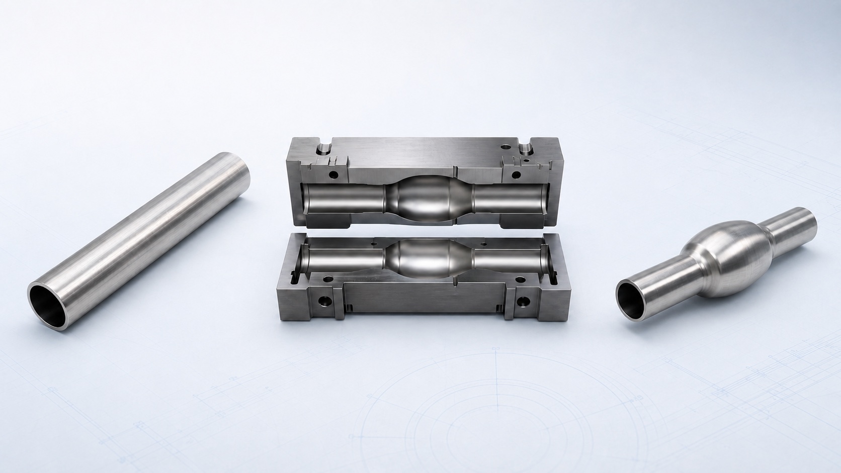
Tube blank, open hydroforming die, and one-piece formed hollow component shown as an engineering sequence
Engineering illustration of the relationship between a starting tube, dedicated die, and formed hollow component.
Die developmentTooling developed around the specified part and tube condition.
Contract hydroformingA defined processing stage based on agreed incoming and delivered states.
Tryout and samplesPhysical parts used to confirm the drawing and project objective.
Repeat productionProcessing against the confirmed revision, inputs, and part state.

Service scope

What ShuiYiYuan can provide

Tube hydroforming is the core operation. A project can cover one defined stage or connect die development, prototype parts, and subsequent production.

When the requirement is to establish hydroforming capability at the customer’s own plant, ShuiYiYuan can also develop project-specific hydroforming equipment and tooling.

01

Hydroforming die development

Development begins with the target component, tube condition, and forming route. The review identifies major section changes, local expansion zones, end conditions, part removal, and the locations that need confirmation during tryout.

02

Custom contract manufacturing

The agreed scope states whether the customer supplies straight tube, a preformed tube, a semi-finished part, or another confirmed incoming condition. It also states the exact condition in which the hydroformed part leaves ShuiYiYuan.

03

Tryout, prototypes, and sample confirmation

A new die moves from design intent to a physical component during tryout. Sample parts confirm the agreed geometry and interfaces and establish which conditions must be fixed before repeat production.

04

Equipment and tooling customization

Customers building their own hydroforming production station can define a separate package for equipment, dies, and related tooling. The delivered equipment scope and site conditions are confirmed during development.

05

From drawing to stable production

When ShuiYiYuan supports the die, samples, and subsequent processing, the conditions established in one stage become the basis for the next. Later changes are reviewed for their effect on the tooling and forming route.

Defined delivery

A clear project boundary before work begins

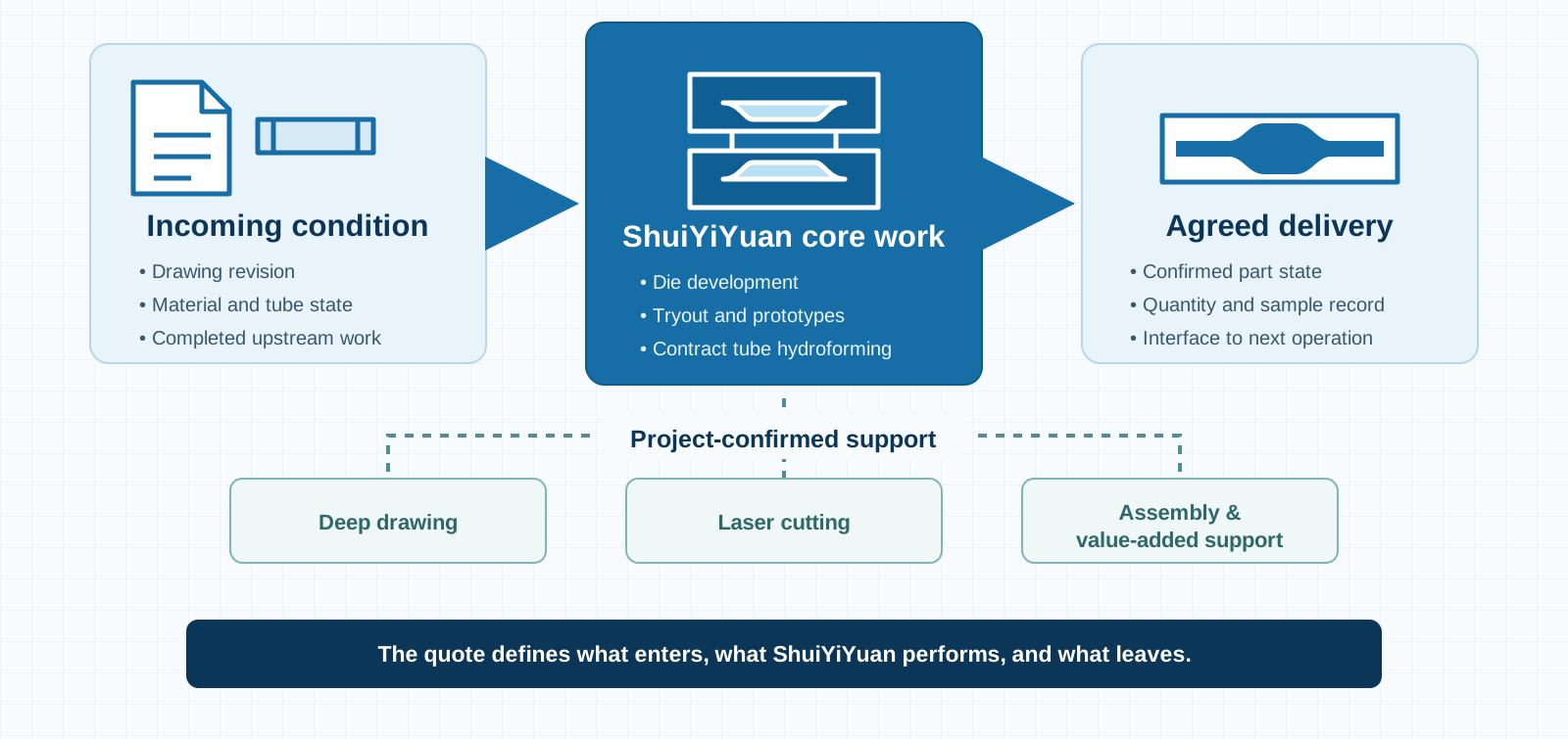
Hydroforming is normally one important stage within a longer manufacturing route. The project record states what enters ShuiYiYuan, what ShuiYiYuan performs, and what leaves for the next operation.

Framework showing incoming project data, ShuiYiYuan hydroforming work, project-confirmed supporting processes, and agreed delivery
01
Incoming condition

Confirm the drawing revision, material and tube state, and completed upstream work.

02
ShuiYiYuan core work

Define die development, tryout and samples, and contract tube hydroforming.

03
Agreed delivery

Record the delivered part state, quantity and sample records, and the next-process interface.

Supporting work confirmed by project
Deep drawingLaser cuttingAssembly and value-added support
Deep drawing, laser cutting, assembly, and value-added support enter the scope only when they are confirmed for the component route.

Project route

From project data to repeat production

The route connects design information, die development, physical samples, and the conditions used for subsequent production.

Five-stage tube hydroforming route from project data to route definition, die development, tryout samples, and repeat production
01
Project data

Drawing, model, material, tube condition, and expected quantity.

02
Route definition

Confirm geometry, interfaces, incoming state, and target delivery state.

03
Die development

Complete the tool concept, manufacture, and tryout preparation.

04
Tryout and samples

Use physical parts to complete the agreed confirmation.

05
Repeat production

Use the confirmed revision, inputs, part state, and quantity plan.

The output of one stage becomes the controlled input for the next; confirmed changes return to route review before production assumptions are updated.
01 · PROJECT DATA

Drawing and target component

A 2D drawing, 3D model, sample images, material, and quantity information identify the target geometry, important interfaces, and current design status. Fixed and adjustable regions can be recorded separately.

02 · ROUTE

Forming route and project boundary

The review considers how the tube reaches the target shape and whether ends, section changes, local features, part removal, and supporting work create conflicts.

03 · PHYSICAL PARTS

Die, tryout, and sample parts

After die manufacture, tryout establishes physical forming conditions. The sample is used to confirm the drawing and project objective, including any customer-run assembly or functional test.

04 · PRODUCTION

Repeat processing after confirmation

Later lots use the confirmed drawing, material, starting tube, and process conditions. A change that affects forming or delivery is reviewed separately from recurring production.

Part fit

Part geometries relevant to tube hydroforming

Hydroforming becomes relevant when a closed tube blank has to form a more complex hollow shape. The component name alone does not establish process suitability.

Four engineering silhouettes showing multiple section changes, local expansion, non-round section, and an integrated hollow form
Multiple section changes

Several cross-section transitions appear along one continuous tube.

Local expansion

A controlled bulged region is formed within a tubular component.

Non-round section

The tube moves from round to oval, rectangular, or another target section.

Integrated hollow form

Several geometric or functional regions are combined in one hollow component.

These are geometry patterns for review, not a promise that every similar part can use the same forming route.

Typical review candidates

  • Tubular parts with several cross-section changes along their length.
  • Hollow components with local expansion, bulged regions, or non-round sections.
  • Parts that integrate several geometric or functional regions into one hollow structure.
  • Existing routes made from several separate pieces where an integrated hollow form is being evaluated.

The complete route still controls the decision

Suitability depends on the target geometry, specified material, starting tube, production quantity, and the complete manufacturing route. A simple constant-section tube or a part that only needs conventional bending does not automatically gain a better route from hydroforming.

Material scope

Materials reviewed for hydroforming projects

Grades and conditions within one material family can behave differently. Project conclusions are based on the specified material, starting tube, and part geometry.

MaterialBasic project conditions considered
Q235B carbon steelMaterial condition, starting tube, section change, and target structure.
Stainless steelGrade and condition, tube state, local features, and delivered requirements.
Aluminum alloySpecific grade and temper, target shape, material flow, and tryout validation.
High-strength steelStrength grade, tube and seam condition, local deformation, and critical structural zones.

Swipe horizontally to view the complete table.

Applications

Automotive parts and other hollow structures

Confirmed automotive product directions include exhaust pipes, chassis parts, body structural parts, seat frames, instrument-panel crossmembers, and battery-pack enclosures. These names cover different structures and delivery requirements; they are not standard products with one shared process specification.

Stainless-steel press-fit pipes, liquid-cooling manifolds, and internal server cooling lines may also contain local sections or shaped hollow features that require forming review. They enter this service scope only when hydroforming is part of the component route. Complete piping manufacture, connection methods, hydrostatic testing, and system-level validation are defined separately for the relevant liquid-cooling project.

Supporting work

How supporting processes enter the route

Deep drawing and laser cutting are available when they support a hydroforming requirement. Assembly and other value-added work are defined for the specific component rather than assumed in every quotation.

01

Deep drawing

Used for associated formed metal structures when the confirmed component route requires it.

02

Laser cutting

Used for agreed contours, holes, or trim work in the sequence defined for the part.

03

Project-specific support

Assembly and value-added support are included only after the delivered condition and responsibility are confirmed.

Confirmation and delivery

Samples and repeat production remain connected

The sample stage establishes what the physical part must confirm. Production then follows the released version and agreed input and delivery conditions.

Sample confirmation

The agreed scope can cover outer shape, critical dimensions, interfaces, assembly locations, or customer functional testing. Customer-supplied material and semi-finished conditions also form part of the sample result.

Stable delivery

After production release, ShuiYiYuan performs hydroforming against the confirmed version and delivered conditions. Prototype work, recurring parts, and later engineering changes remain separate activities.

Related technical resources

Continue with cost or drawing review details

The service page defines what ShuiYiYuan can take on. The Resources articles explain the engineering and quotation questions in greater depth.

Start a project

Send the drawings and define the next project stage

ShuiYiYuan will first identify whether the immediate stage is drawing review, die development, tryout samples, equipment and tooling customization, or repeat contract manufacturing. The response can then define the service scope, open interfaces, and the next deliverable.

Available project information
  • 2D drawing, 3D model, or sample information
  • Material and incoming tube condition
  • Critical interfaces and target part state
  • Prototype or expected production quantity
  • Required delivered condition
Send project details