
A mounting system designed for die changes
The patent addresses the work involved in removing conventional bolted die mounts. Its background identifies cumbersome disassembly and damaged bolts as obstacles to replacement. ShuiYiYuan's design uses sliding connections for installation and retractable locking blocks for fastening, separating withdrawal of the die from release of its locks.
The lower die mounts on one plate and the upper die beneath another. Front and rear support plates connect the dies to these mounting plates. Blocks fixed to the front and rear of each die house the screws, moving blocks and locks. Retracting the locks releases the connection between the die, its supports and the mounting plate.
The distinctive features are in these mounting interfaces: guides establish the withdrawal path, locking blocks secure the installed die, and locating blocks and stops restrain rotation of the locking screws.
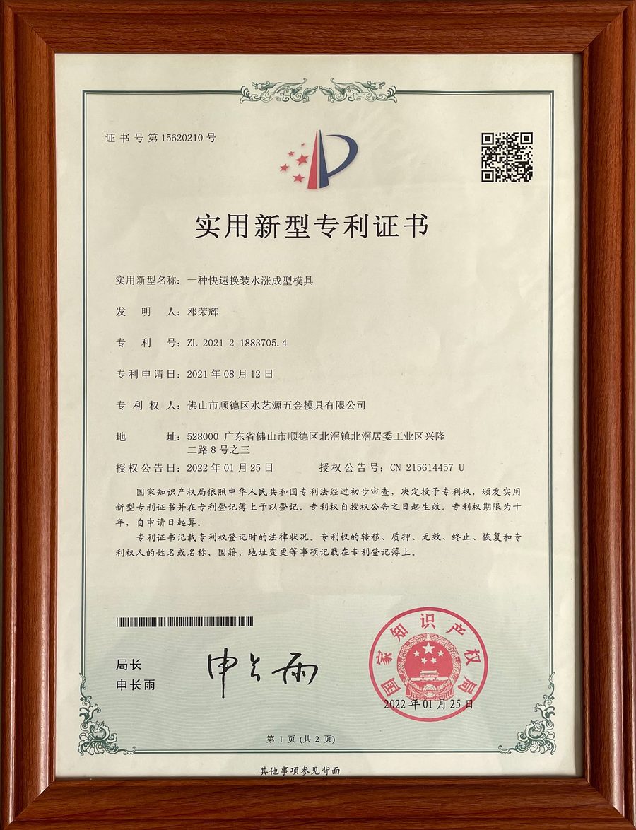
Patent record
| Field | Details |
|---|---|
| Title in Chinese | 一种快速换装水涨成型模具 |
| Patent type | Chinese utility model |
| Patent number | ZL 2021 2 1883705.4 |
| Grant publication number | CN215614457U |
| Filed | 2021-08-12 |
| Grant published | 2022-01-25 |
| Inventor | Deng Ronghui (邓荣辉) |
| Patentee named on the certificate | Foshan Shunde ShuiYiYuan Hardware Mould Co., Ltd. |
The grant publication number can also be searched in CNIPA's patent search system.
Sliding guides, locking blocks and anti-rotation stops
T-shaped locating blocks on the dies engage matching slots in the mounting plates. Separate T-shaped sliders connect the support plates to the same mounts. These guides constrain the dies and supports independently while retaining them on their sliding interfaces.
Each locking screw engages a moving block that extends or retracts the locks through matching holes and slots in the supports, die and mounting plate. A round head at the end of the screw provides the adjustment point. A spring beside the moving block compresses with its travel. Threaded actuation is retained, while the locking blocks make the connection across the assembled parts.
Locating slots around the screw head accept hinged blocks that restrain unwanted rotation. An additional sliding stop holds those blocks in place and has its own T-shaped guide. The design thus includes hardware for retaining the locked position as well as for sliding the die into and out of its mount.
Design features
Separate guides for dies and supports
The dies and support plates have their own T-shaped guides. Each can move in its intended direction while remaining constrained by the mounting plate. The guiding surfaces establish their positions during installation, rather than leaving location solely to the fasteners.
Locking with restraint against screw rotation
The locking blocks secure the die to its supports and mounting plate. Locating blocks and a sliding stop restrain the round screw head, adding anti-rotation hardware to the releasable connection.